Mastering Electrical Troubleshooting: How to Use a Multimeter for Continuity Testing
Mastering Electrical Troubleshooting: How to Use a Multimeter for Continuity Testing
When the lights flicker, circuits fail, or a relay refuses to engage, pinpointing the root cause can feel like searching for a needle in an electrical haystack. But with a calibrated multimeter set to continuity mode, what once seemed impossible becomes straightforward and reliable. This indispensable tool transforms troubleshooting from guesswork into precision, empowering electricians, hobbyists, and DIY enthusiasts to diagnose faulty connections, breaker issues, and open circuits with confidence.
Understanding Continuity Testing: The Foundation of Electrical Diagnosis
At its core, continuity testing measures whether an electrical path exists and is intact. In electrical theory, continuity refers to the uninterrupted flow of current through a conductor—essentially a check that wires, connections, and components form a complete, low-resistance circuit. A multimeter in continuity mode functions like a sensitive echo, emitting a beep when it detects a low-resistance path (typically below 1 ohm), confirming a solid connection.When no beep sounds, the absence indicates a break, high resistance, or an open circuit. “Continuity testing isn’t just about finding the broken wire—it’s about verifying system integrity,” explains James Holloway, a licensed electrical technician with over a decade of field experience. “Even a tiny loss in conductivity can cause failure, and a multimeter reveals precisely where that slippage occurs.” This simple yet powerful test underpins countless electrical checks, from verifying solder joints on PCBs to inspecting wiring in home rewiring projects.
Without it, troubleshooting would rely solely on visual inspection or trial and error—both prone to error and inefficiency.
Choosing the Right Multimeter for Continuity Checks
Modern digital multimeters dominate the market for continuity testing, offering precision and user-friendly interfaces. While analog meters once served the role, their limited accuracy made them unsuitable for most troubleshooting needs.Today’s digital multimeters deliver digital readouts, often with auto-ranging capabilities that simplify operation, especially for beginners. Look for models with a dedicated “continuity” or “tone” function—typically marked with a diode symbol or a beep tone icon. Resolution below 1 ohm ensures sensitivity to even the tiniest gaps, while a high-impedance input prevents self-discharge and false readings.
Key specifications to consider include: - **Measurement range**: A continuous low-range (e.g., 200 mΩ to 1 Ω) is ideal for most connectivity tests. - **Tone output**: Provides auditory feedback when continuity is detected, useful in loud environments. - **Comprehensive testing**: Some models combine resistance, capacitance, and conductivity checks for expanded diagnostics.
Calibration and battery life are critical—ensuring your multimeter remains accurate and reliable. A dead battery mid-test can derail critical diagnostics; hence, regular battery checks and proper storage in a dry, cool environment extend device lifespan and consistency.
Step-by-Step: Executing a Reliable Continuity Test
Conducting a continuity test with a multimeter is more instinctive than complex, yet precision demands attention to detail.Follow these verified steps to ensure consistent, accurate results: 1. **Power down and isolate the circuit** — Safety demands switching off power at the source and disconnecting components to prevent accidental shorts. 2.
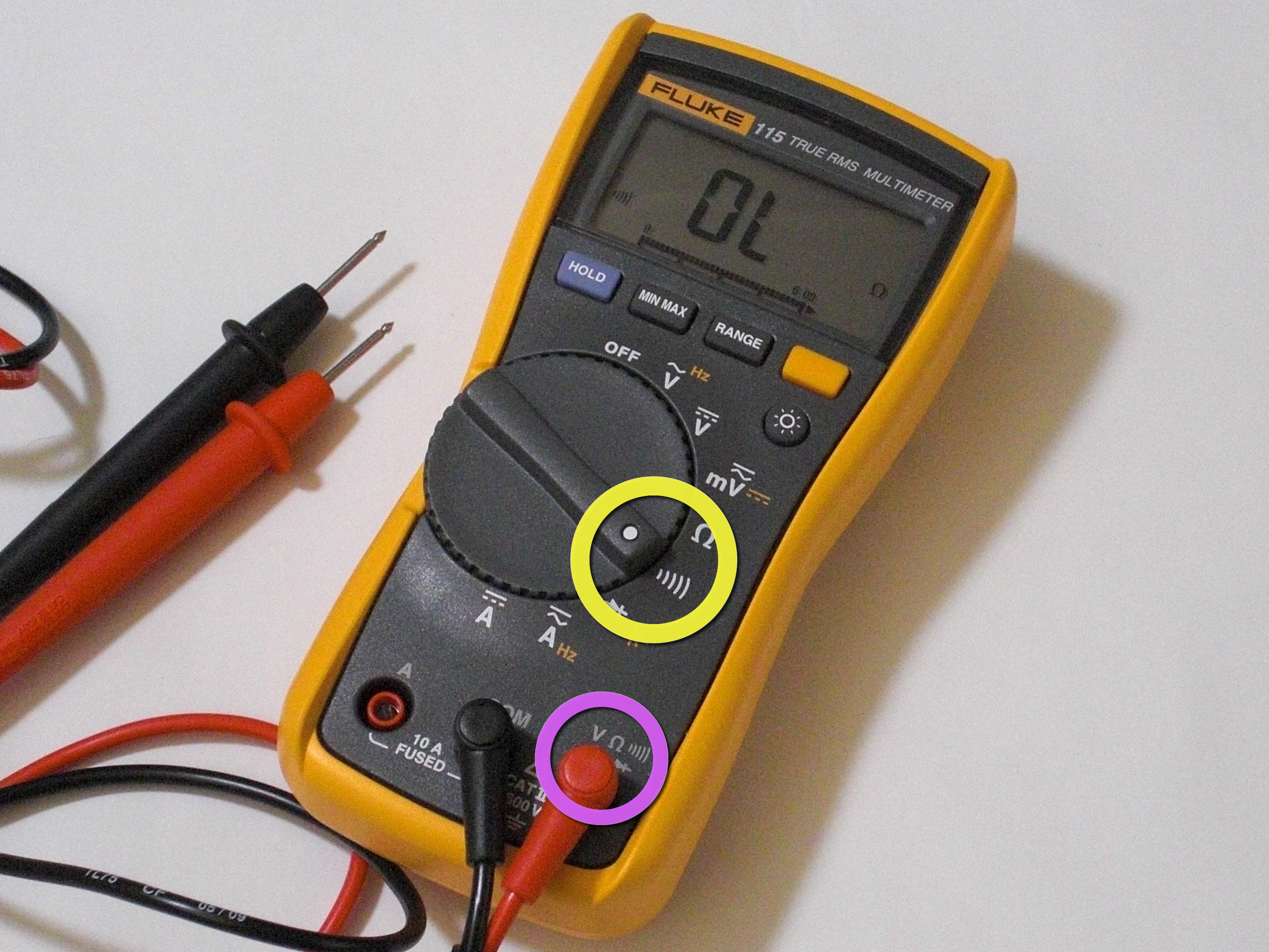
**Select continuity mode** — Rotate the dial to the multimeter’s continuity setting (often marked with a wave symbol or ⎗). 3. **Prepare the test points** — For a wire or junction, remove connectors and ensure bare metal contacts are exposed—moisture, oxidation, or insulation must not impede the test.
4. **Make first contact** — Touch one probe to each end of the test path. In a broken or open circuit, no sound should trigger.
5. **Interpret results** — A continuous tone or beep confirms a complete path; silence signals an open circuit. 6.
**Verify connections** — Recheck polarity in diodes or semiconductors—some components require directional flow. This process reveals more than just whether a connection exists—it illuminates hidden faults like corroded terminals or damaged strands. As technician Holloway notes, “Continuity testing isn’t just about sound; it’s about understanding the lifeblood of a circuit.”
Applications Across Industries: More Than a DIY Trick
While popular among home electricians and hobbyists, continuity testing with a multimeter is foundational across professional domains.In residential settings, it identifies faulty switches, burnt-out outlets, or damaged appliance wiring. In industrial plants, it ensures reliable machinery connections and safety interlock systems. Electricians on construction sites use it to validate initial wiring integrity before commissioning.
Even renewable energy technicians rely on it during solar panel array and inverter installation to confirm complete connectivity. “Whether troubleshooting a standalone garage circuit or diagnosing a smart home’s complex network,” explains electrician Lena Cruz, “the multimeter’s continuity function cuts through ambiguity. It’s the first diagnostic step that saves time, reduces guesswork, and prevents costly mistakes.” Advanced users integrate continuity checks with other multimeter functions: measuring voltage to confirm incoming power before testing connections, or using resistance mode to expose degraded insulation.
This layered approach creates a holistic diagnostic framework.
Common Pitfalls and How to Avoid Them
Even seasoned users encounter challenges. Misinterpreting resistance values is a frequent error—multimeters in continuity mode report low dB readings, not absolute ohms; a “2 Ω” result doesn’t mean failure, just reduced conductivity.Conversely, assuming silence guarantees integrity is dangerous—extended leads or poor contact can register mute despite an open path. Also, multimeters struggle with very high-resistance breaks beyond their range; continuity tests often flag only moderate losses. To mitigate issues: - Use a known-good reference wire for warm-up and baseline comparison.
- Clean contact points with conductive paste or sandpaper before testing. - Note environmental factors—humidity and temperature affect resistance—but continuity is largely unaffected. - Always test with power isolated to prevent misleading results from live circuits.
These precautions ensure consistent, trustworthy readings across diverse operating conditions.
Final Thoughts: The Multimeter’s Continuity Core in Modern Electrics
The multimeter’s continuity testing capability remains a cornerstone of electrical troubleshooting—democratizing precision diagnostic power for both pros and passionate amateurs. It transforms vague circuit failures into solvable issues through a simple, intuitive tool that delivers immediate, credible data.As technology evolves, so too does its role: from basic check to integral part of layered diagnostic workflows in smart homes, renewable systems, and industrial


Related Post

Jamaicans Crossing Mexico: A Journey Through Risk, Resilience, and Cross-Border Realities

The Untamed Hindi Dubbed: Episode 5 Unveiled – A Fresh Chapter in Global Storytelling

Marquense and Mictlán: Unveiling the Ancient Cosmos of the Marquense-Mictlán Mythos

Wa We: The Unsung Technical Powerhouse Redefining Smart Device Ecosystems